- Home
- Boat Building
- Boat Plans
- Spiling
- Diagonal Scale
- Lofting
Lofting Boat Plans
All boat plans
required lofting in the days
before CAD (Computer Aided Design), when the plans were hand drawn.
The job of the 'Loftman' was to scale up the original drawings to full size.
Drawing the plans full size had two main objectives.
- To identify and correct any mistakes on the original drawings.
- And to create full sizes templates from which to cut the timbers.
Fortunately, for today's builders, CAD drafting should remove any of the mistakes inherent in hand draw plans.
Many plans are supplied with full sized patterns, particularly for small boats.
And kit boats are supplied with the parts already cut out or at least marked on the wood.
However for anyone who does need to do their own lofting, be assured there is no magic art involved.
But it does take a couple of attributes.
- An obsession for accuracy.
- And a good eye for a fair curve (nothing to do with lechery, or is it?).
You will also need a suitable space to work, a few tools and an understanding of how plans are drawn.
The Lofting Floor.
The name lofting comes from the space where traditionally the 'mold loftsman' worked.
Like a sail loft this had to be a large open area where the work could be spread out flat without any obstructions.
- So your first objective must be to have access to an area which is longer than the boats length and wider than the boats height.
- The floor needs to be as flat and level as possible with no bowing or warping.
- It needs to be undercover to protect it from the elements.
- It can be covered with either plywood or chipboard on a level bed of 2'x4's.
- Nail a base line timber lath along the full length, check this thoroughly for straightness with a stretched string.
- Be aware that expansion and contraction due to humidity could cause considerable differences across a long floor.
- Paint the floor white.
- Provide good lighting so you can read those plans and make those measurements accurately.
Tools.
Most of the tools you will need are for marking and measuring.
- Tape measures, one long one and a shorter steel tape measure.
- A folding rule preferably made of steel.
- 90 degree set squares, one medium sizes preferably of steel and one large wooden one.
- Straight edges, at least one long one and a shorter one
- Claw hammer
- Nails
- String
- Pincers, for drawing nails.
- Pencils
- Splines
Splines.
"If a man is to be
obsessed by something, I suppose a boat is as good as anything, perhaps
a bit better than most."
(E.
B.
White)
The Splines are long strips of springy material used for drawing curves.
It is preferable to have three long splines and several shorter lengths.
The longest should be longer than the length of the full sized boat.
Traditionally splines were made from fine straight grained wood such as fir, which is available in long lengths.
Sprung steel and fiberglass strip can also be used.
The advantage of wood is that it can be tacked to the loft floor.
Also see 'Drawing Bow'.
Plans.
The plans are a set of line drawings.
The lines of the boat are drawn over a grid.
The plan will show three views, a plan, a profile and a body plan which, is the view from bows on.
Heights are measured vertically off the base line, though sometimes from a datum waterline.
The hull length will be divided vertically into 'stations', positioned in relation to the centreline.
These station lines are datum lines and are not necessarily the positions of the frames.
The Grid.
The next job is to transfer the grid full sized in to the floor.
Check the base line is straight by stretching the string along it.
Then erect the center line at 90 degrees to the base. Check this by using Pythagoras' 3-4-5 triangle.
Once the first set of grid measurements have been made and checked they can be transferred to a baton which can then be slid along to mark the rest.
Label all the grid lines as you go.
Constantly check and re-check your measurements.
All diagonals must be marked accurately as these cannot be checked for parallel against anything.
Once the grid is set up you can then interpolate and draw in the frame locations and the curved shapes by joining all the relevant points using the flexible splines.
The Offsets.
Most sets of plans will also have a table of offsets.
With a full set of plans these are more of a convenience than a necessity.
They show the dimensions of the boat taken from fixed datum points
You need to check if the dimensions have been taken to the outside or the inside of the planking.
However if these have been taken from the line drawing they may contain inaccuracies.
But, this is why you are drawing them full size anyway, to rule out any drawn errors.
The traditional way to show dimensions in the offsets for a ‘station’ is in "feet" - "inches" - "eighths of an inch.
For instance; O-6-2 = 6 and 1/4 inches, 10-1-6 = 10ft,1and 6/8 inches, 13-0-2. = 13ft and 1/4inch.
Just to complicate things, if there is a + or a – after the last number that means you should add or subtract 1/16 of an inch from the last number.
So, 0-6-2+ would work out as 6 and 5/16 inches.
Patterns.
Once you have your plan lofted out full size you can now use it to make templates for many of the parts.
Patterns for the keel, the stem, beams, and combings can be accurately made from stiff material such as plywood.
This will make marking the timber prior to cutting much easier.
The template is also a handy way to check the timber for any knots or splits which might fall in an area where a rabbet might need to go.
The most accurate way to assemble molds and frames is to do it on the loft floor directly over the lines.
NATIVE ASYNC

Previous posts
See What Others Have Posted
RIVER DRIFTER
The line drawing dimensions in 'DRIFT BOATS AND RIVER DORIES' are stated as; O-6-2 AND 10-1-6 OR 13-0-2.
Can someone crack this code for me please? …

Recent Articles
-
Wooden Boat Events 2024
Apr 14, 24 05:15 AM
Wooden Boat Events 2024 calendar, traditional and classic boat festivals and regattas from around the world
You might like these
Plywood and Veneer Guide for Marine use.
A guide to plywood for boat building and why you should use the best marine grade you can afford.
DIY Woodboat Building Questions
Woodboat building questions a Forum for wooden boat building, plans, lumber, caulking compounds and other boat building problems.
Boat Books for Wooden Boat Builders
Boat Books a series of boat books based on some of the 1960's, classic, Free Boat Plans that were published in magazines such as "Popular Mechanics", "Popular Science" and the "Boat Builder Handbook".
Build a Boat, tips for the DIY Wooden Boat Builder.
How to Build a Boat, Wooden Boat Building methods for the DIY, backyard, self-builders explained, carvel, lapstrake and plywood
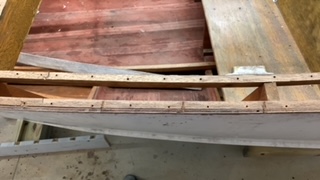
Clench Nails, Fastening for Small Wooden Boats.
How to use Clench Nails, these provide a fast reliable method for fastening small wooden boats.
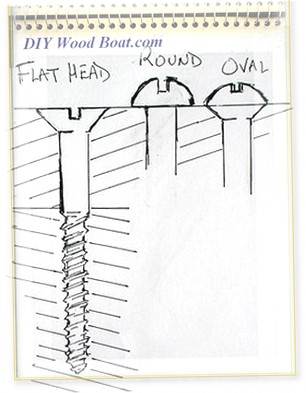
Wood Screws for Boat Building and Repair.
Wood Screws are the most widely used and versatile fasteners used on wooden boats. Which type to use and how to use them


Recent Articles
-
Wooden Boat Events 2024
Apr 14, 24 05:15 AM
Wooden Boat Events 2024 calendar, traditional and classic boat festivals and regattas from around the world -
14’ 1956 Chris Craft, side rail how should it be attached?
Apr 12, 24 03:38 AM
 Removing the old side rail most of the screws went between the top deck/skin 1/4” plywood and the side of the hull. See photo, is this correct? I would
 -
How to laminate plywood on the hull
Apr 10, 24 03:46 AM
I'm working on replacing the bottom of 18' 1969 runabout that has a deep-V plywood hull. It had a 1/2 mahogany plywood bottom that they somehow got to
You might like these
Free Motorboat Plans
Free Motorboat Plans for the backyard home builder, build your own speed boat, cabin cruiser, runabout or utility boat using these simple plywood designs.
Wooden Boat Kits.
Wooden boat building is easy and inexpensive with wooden boat kits. From row boats and kayaks to sailing cruisers, boat to be proud of
Supplies for Wooden Boat building and Maintenance
Supplies for Wooden Boat Building and restoration, how to choose the materials and marine chandlery for your project.
DIY Woodboat Questions
Woodboat questions and answers forum for all Wooden Boat owners, advice and opinions on all aspects of wooden boat building, restoration and maintenance.
Small Boats, Made of Wood
What Everybody ought to know about building Small Boats, guidance and tips for self-building or restoring.
Sailboat Plans
Free Sailboat Plans for the backyard home builder, build your own wooden sailboat using these simple plywood designs.


This work is licensed under a Creative Commons Attribution-ShareAlike 2.0 UK: England & Wales License.
I am perfectly aware that the majority of Wooden Boat aficionados are sensible folk.
However, I need to point out that I am an amateur wooden boat enthusiast simply writing in order to try to help other amateur wooden boat enthusiasts.
And while I take every care to ensure that the information in DIY Wood Boat.com is correct, anyone acting on the information on this website does so at their own risk.